teds fabrication what gauge wire to use when installing
Which Connection Cables to Use for Electrical Foil Strain Approximate Applications Structural Tests/Immovability Measurements
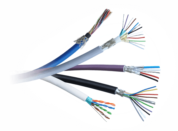
There are a lot of cables available in the market which may be used for strain gauge applications.
The success of a measurement depends on the right connection cables. Not only do they have to transfer the measurement signals from the sensor to the DAQ organisation, merely they also have to avoid interference signals and resist stress during their utilize.
Ideally, the cable should not have influence on the strain measurement. In reality, however, cables/wires could have an influence on the measurement betoken. The effects of the wires can be minimized to an acceptable level. HBM offers a broad choice of different measurement cables and small-scaled stranded wires for a wide range of applications. There are some important points to consider when selecting the correct cable for your awarding:
Multi-stranded wires with tin coatings are more often than not used for strain guess applications. Usually, copper conductors are used as wires (most common standard considering of skillful cost-to-conduction ratio).
The strain measurement signal in a quarter-span configuration is very sensitive:
- A typical excitation voltage for a strain approximate quarter span is ii.five V
- Strain applied to the strain approximate creates a bridge voltage output that is relatively depression!
(0.000125V for 100µm/grand strain respectively 0.0025V for 2000µm/thousand strain). This is visualized in the graphs beneath for a typical quarter-span application.
This measurement voltage betoken must non be interfered with by external signals. This is the reason why the right measurement cable is absolutely necessary!

Bridge voltage output signal with 100µm/m strain signal. The span excitation voltage (red) is very pocket-sized in comparing to the excitation voltage (blue):

2 Interferences/Impacts on the measurement cablevision

3 The requirements on a cablevision for strain gauge applications at a glance
- Low resistance (generally) and low-capacitance
- Good insulation
- Good mechanical protection
- Good handling (flexibility)
- Suitable working temperature range and low influence of temperature changes
- Good solderability of the wires
- Condom requirements (flame-retardant,etc.)
- Mechanical robustness
- Robustness against different media (water, oil, solvents,etc.)
4 Ecology requirements on cables/wires:
The coating and the wire insulation influence the temperature range to which they tin can exist exposed. The post-obit diagram shows the typical temperature range of cables depending on their coating.
-
For most applications, PVC-insulated cables are suitable; they offer an excellent toll-to-performance ratio (upward to eighty °C)
-
For medium temperatures, TPE cables are a good option (upwardly to 150 °C)
-
For higher temperatures, we recommend using PFA cables (upwardly to 250 °C) or polyimide-coated cables (>300 °C)
-
At low temperatures, standard cables can get breakable. This is peculiarly critical when they are used in dynamic test environments. Using cables with a PTFE, PI, or glass fiber sheath is recommended in this case.
There are many more requirements on cables such equally resistance confronting different fluids and flammability. The following table provides an overview of typical cable jackets/insulation materials and their temperature range:

5 Diameter of usher:
-
The diameter of the wire has a huge influence on the resistance. The excitation voltage of a strain gauge bridge generates a current which heats up the conductor. The smaller the bore the college the temperature increase on the wire.
-
To minimize errors, the largest possible wire diameter shall exist used to minimize the consequence of lead-wire resistance in strain gauge applications and the thermal effects of the cable.
-
In some applications, thin cables are necessary to reduce inertia/weight or allow for a small bending radius.
-
Long sensor cables generally require bigger wire diameters.
A modest-diameter cablevision shall be used at the strain estimate to reduce the solder amount and parasitic stress on the estimate.Still, it must be taken into business relationship that these sparse wires touch the circuit stability and sensitivity.
- A solder terminal can be used as the point of intersection between the measurement cable and the connexion wire of the strain gauge. This method enables a transition from a small-diameter cablevision to a cablevision with a thicker bore:
Strain gauge connected with HBM's patented 4-wire engineering science:

1 Thermally strip 5mm of insulation off the wire to be attached to the strain gauge.
Thermal stripping prevents damage which tin can occur from mechanical stripping with pliers.
2 Tin the wire end with solder.

3 Trim the tinned conductor and then that it does not extend the guess carrier after soldering (ane-3mm depending on the strain-judge geometry).

1-wire: Connections betwixt strain gauges and solder terminals

three-/iv-wire: For quarter-bridge applications (only 4-wire shown) or total bridges:

five-wire: One-half-bridge applications

6-wire: Full-bridge applications

- Generally, keep the length equally brusque as possible to minimize thermal and electromagnetic interference.
- For long distances, choose bigger conductor diameters to keep the influence of resistance depression.
- If signals are transmitted with high frequency and DC too a low-capacitance wire is recommended.
DC amplifier
- Contains a generator providing a stabilized DC voltage for feeding the bridge circuit
- Amplifies static and dynamic signals up to loftier frequencies
- In practise: usually max. ten kHz; higher frequencies consequence from interference pulses which should not influence the measurement signal
Disadvantage: Interference (acquired by electric or magnetic fields likewise equally thermoelectric and galvanic voltages in the measuring circuit) is fully amplified.
- Error in the measurement result
- Electrical or magnetic shielding is required
- Or mathematical correction of thermoelectric voltages
Carrier-frequency amplifier
- Generator supplies avoltage- and frequency-stabilized alternating voltage to supply the bridge circuit
- Output voltage = alternating voltage whose amplitudes are proportional to a bridge unbalance (amplitude modulation)
- Frequency selection and so that merely the frequency of the supply voltage is amplified (interferences accept no influence)
- Common carrier frequencies:
- 225 Hz: Measurement of static and quasistatic processes (upward to nine Hz)
- v kHz: Measurement of static and quasistatic processes (upwardly to ane kHz)
Disadvantage: Express bandwidth
8 Cable protection around the strain guess for harsh weather condition
- Moisture-proof connexion betwixt the wire and the protective coating. Therefore, maximum adhesion betwixt the covering agent and the connection cable and the material surface is required
- Fluoropolymer cables shall exist etched previously to allow proper sealing of the measurement cable
- Special cables with water-blocking tape are recommended for submersion under h2o (please contact the HBM Service Team)
- Ensure a minimum length of the protective agent effectually the cablevision access to maximize the creep distance and ensure that critical points are sealed
9 Exam dynamics
- For high-dynamic measurements, jumper wires should be used. Jumper wires consist of many thin stranded single wires which are surrounded by actually flexible insulation.
- Solid wire shall only to be used on static objects (e.k. for span interconnections)

10 Decision
- Use the maximum cable diameter
- Use low resistance and depression capacitance cable
- Minimize cablevision lengths if possible
- Use minimum bore on the strain gauge directly
- Cull the right cablevision depending on your test scenario
- Use flexible cables
- Use cables with a conductive the shield
- Ensure proper grounding for shield
- Ensure Faraday cage for the measurement signal chain
- Careful routing of wires
- Twisted wires
- Do not lay primary ability cables shut to the measurement cable in one cable (90° crossing of power lines and measurement signal lines)
- Remove noise sources
- Use carrier frequency amplifiers
- Employ the correct filters
Related products
hughesactoluesce00.blogspot.com
Source: https://www.hbm.com/en/8250/wiring-of-strain-gauges/
0 Response to "teds fabrication what gauge wire to use when installing"
Post a Comment